Introduction
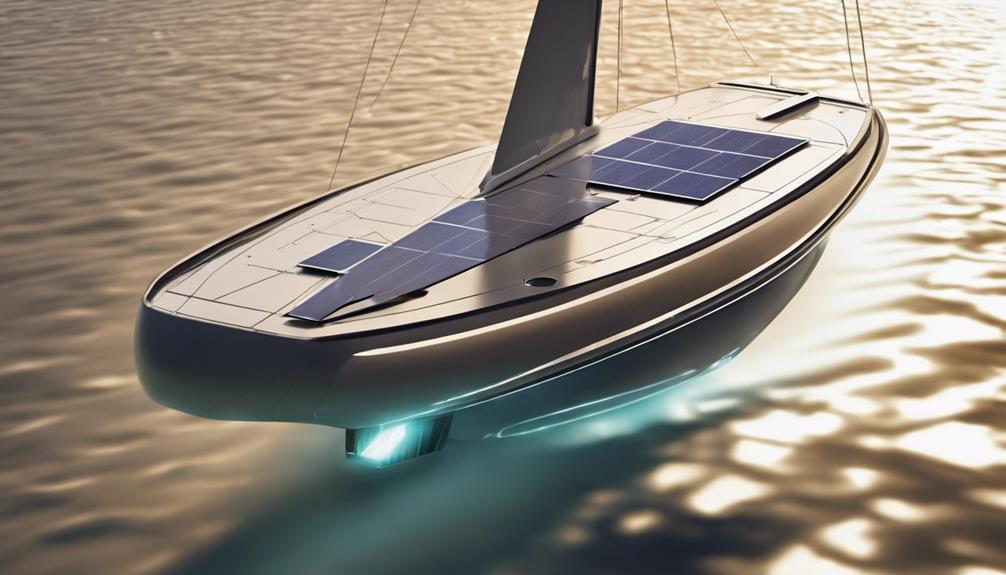
This guide explains how solar power systems for caravans (the common US term is RV) work, how to size them, and how to select and install components safely. Solar on a caravan is a system: PV array → solar charge controller → house battery → DC loads and/or inverter → AC loads. Panels alone don’t provide predictable power without a battery and controller.
How a caravan solar system works
Basic energy flow:
- PV array (roof‑mounted or portable) generates DC power.
- Solar charge controller (MPPT or PWM) regulates charging into the house battery.
- House/auxiliary battery stores energy and supplies DC loads or an inverter for AC loads.
- Additional charging may come from a DC–DC charger (alternator), shore power charger, or generator.
Step 1 — Start with a load audit
Estimate daily energy use before selecting panels or batteries. Use:
Energy per day (Wh/day) = appliance power (W) × operating time (hours/day)
| Appliance | Power (W) | Hours/day | Daily energy (Wh) |
|---|---|---|---|
| 12 V fridge (average) | 60 | 12 | 720 |
| LED lights (4×5 W) | 20 | 4 | 80 |
| Water pump | 50 | 0.25 | 12.5 |
| Phone/laptop charging | 30 | 3 | 90 |
| Inverter standby & losses | 15 | 24 | 360 |
| Total | 1262.5 Wh/day |
Notes: measure actual fridge cycling where possible. Inverter losses and parasitic draws are real and should be included.
Step 2 — Estimate solar production
Convert daily energy need into PV-array capacity using a location-specific solar-resource model such as NREL’s PVWatts V8. Conceptually:
Daily energy ≈ array capacity (Wp) × location-specific solar resource × total system derating
Illustrative example (assumptions shown):
- Needed daily energy: 1,300 Wh (rounded from table above)
- Assumed effective solar resource: 4.0 kWh/m²/day (varies by site and season)
- Assumed system derating (soiling, temperature, wiring, partial shading, controller losses): 0.70
Required array ≈ 1,300 Wh ÷ (4.0 kWh/m²/day × 0.70) ≈ 465 Wp. (Assumptions: clear-sky mid-latitude average; use PVWatts V8 for site- and month-specific estimates.)
Do not treat this number as a guarantee—PVWatts gives estimates; real yield depends on orientation, tilt, shading, and weather.
Step 3 — Size the battery bank
Decide how many days of autonomy you need, and use usable battery capacity, not nominal amp-hours. Example assumptions:
- Night/backup energy need: 1,300 Wh.
- Desired one day autonomy without solar: 1,300 Wh.
- System nominal voltage: 12.8 V (common for LiFePO₄).
- Assumed usable fraction: use manufacturer’s permitted SOC (example uses 80%).
Battery Ah required ≈ 1,300 Wh ÷ 12.8 V ÷ 0.80 ≈ 127 Ah usable. If using LiFePO₄, the manufacturer’s permissible depth-of-discharge and BMS behavior determine usable capacity—do not assume a universal 90%.
Step 4 — Choose panels and mounting
| Feature | Rigid framed | Flexible |
|---|---|---|
| Durability | Generally higher | Varies by quality |
| Weight/height | Heavier, taller | Lighter, low profile |
| Roof compatibility | Requires flat stanchions | Good for curves/limited space |
| Heat dissipation | Better when ventilated | Can trap heat |
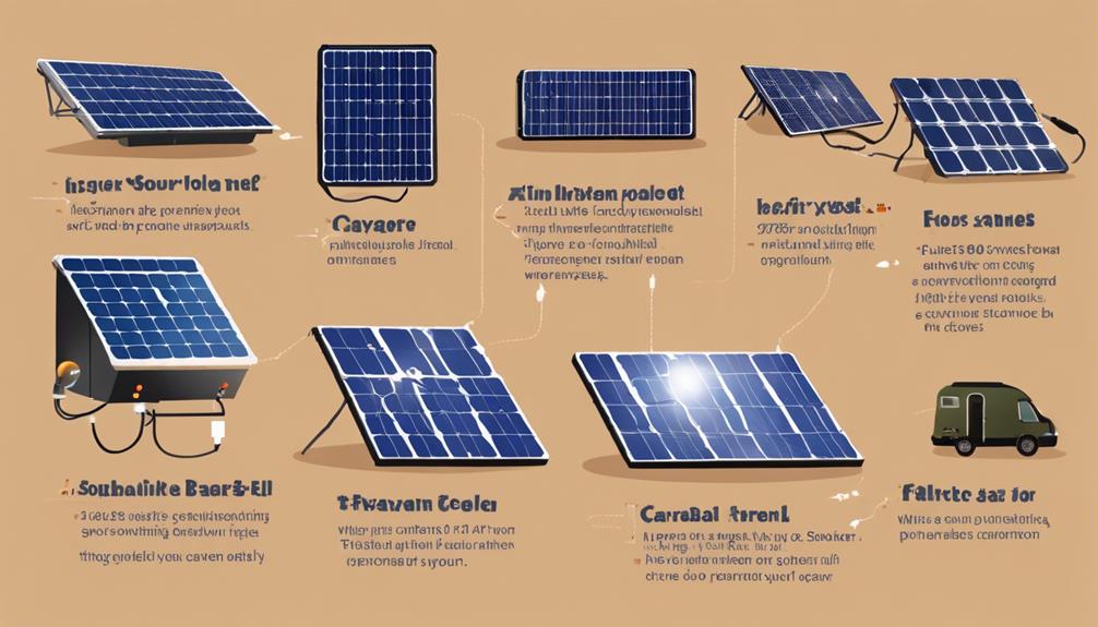
Consider portable panels if you need to avoid roof shading or want to angle panels toward the sun while parked.
Step 5 — Choose the charge controller
MPPT controllers typically extract more energy than PWM in modestly sized or higher-voltage arrays and when conditions vary. Choose a controller rated for:
- Maximum PV input voltage (check cold-weather Voc)
- Maximum charge current (respect battery max charge current)
- Compatibility with battery chemistry and BMS signaling
Follow the manufacturer’s sizing rules rather than relying on a single shortcut formula.
Step 6 — Alternator and shore charging
Use a DC–DC charger when you need controlled charging from the vehicle alternator, when dealing with smart alternators, or when isolation is required. Verify alternator capacity, vehicle manufacturer restrictions, cable sizing, and whether the charger supports your battery chemistry and low-temperature protection.
Step 7 — Inverter planning
Size for continuous AC load and surge/start currents. As a rule of thumb, a 1,000 W AC load can draw roughly 80–100 A from a 12 V battery once conversion losses are included—confirm with the inverter’s efficiency curve. Ensure proper cable sizing, fusing, ventilation, and an appropriate transfer/isolation arrangement for shore power.
Example system scenarios (illustrative)
| Use case | PV | Battery | Notes |
|---|---|---|---|
| Light weekend | 200–300 Wp | 100–120 Ah lead/AGM or smaller LiFePO₄ | Mostly 12 V loads; shore as backup |
| Part‑time boondocking | 400–600 Wp | 150–300 Ah LiFePO₄ or equivalent usable | Combine with DC–DC or shore charging |
| Higher‑demand off‑grid | 800+ Wp | 400+ Ah usable | Likely need generator/shore for A/C or electric heating |
Do not treat these as one‑size‑fits‑all—adjust to measured loads and local solar resource.
Wiring and safety checklist
- Size cables for expected current and voltage drop; place overcurrent protection near the battery.
- Use DC-rated breakers/fuses and correct PV connectors; check polarity carefully.
- Restrain batteries and enclose per manufacturer instructions; include BMS and temperature sensors for LiFePO₄.
- Seal roof penetrations, protect against chafing and vibration, and follow vehicle/roof weight limits.
- Follow applicable standards and get a professional review for high‑current or lithium retrofits—standards referenced here include RVIA (ANSI/RVIA DC Standard, 2025 edition), NFPA 1192 (2026 edition), and the NEC (2026 edition) as of July 21, 2026. These are U.S.-centric references—check local rules.
Monitoring and maintenance
A shunt-based battery monitor gives better SOC and current data than voltage alone. Monitor solar harvest, alternator/shore contributions, and BMS alarms. Periodically inspect connections, roof seals, and panel cleanliness; shading and dirt materially reduce output.
When to use a professional
- High-current inverter systems, lithium retrofits, or multiple charging sources.
- Structural roof work, complex AC wiring, or installations subject to inspection or code enforcement.
- When in doubt about compatibility between battery BMS, charger, and alternator.
Conclusion
Design a caravan solar system by auditing loads first, modeling site-specific production (PVWatts V8 is current for U.S. estimates), sizing usable storage, and then selecting compatible components. Plan for realistic losses, include a backup charge source for cloudy periods, and prioritize safe wiring, fusing, and installation or professional review for complex or lithium installations.