Quick answer: pick the architecture by how you camp
Pick the system that matches your goals, not an advertised wattage. Short summary:
- Day trips: Small portable panel or a compact portable power station for phones, lights, and cameras.
- Weekend camping: Portable power station or modest battery-plus-panel setup; choose if you want expandability or hard-wired 12‑V circuits.
- Multi-day boondocking: Dedicated battery bank, MPPT controller, a PV array sized for local sun, DC distribution, and a suitable inverter.
- Full-time / high-load vanlife or RV: Professionally reviewed, expandable vehicle electrical system with multiple charging sources, monitoring, and structural/mounting review.
The three numbers that matter
- Watts (W): Instantaneous power. “Can I run this now?”
- Watt-hours (Wh): Energy over time. “How much will it use today?”
- Amp-hours (Ah) and voltage: Battery capacities are meaningful only with voltage. 100 Ah at 12.8 V ≈ 1,280 Wh nameplate.
How to calculate daily energy use
Inventory devices and use the basic formula:
Daily energy use (Wh) = device wattage × hours used per day.
If a device is rated in amps: Watts ≈ volts × amps. Separate DC loads (run directly from battery) from AC loads (require inverter). For AC loads, add inverter losses (illustrative: 85–95% inverter efficiency depending on unit and load).
Battery sizing (practical)
Work through these steps:
- Add expected daily loads (Wh).
- Decide autonomy days (how many cloudy/no-drive days to cover).
- Estimate usable fraction from the battery’s documentation (manufacturer-specified usable capacity, not a generic DOD number).
- Apply the formula:
Required nominal battery capacity ≈ daily Wh × autonomy days ÷ usable fraction.
Example notes: LiFePO4 (LFP) often has high usable fraction and long cycle life, but many products restrict charging below a cold threshold (example: some manuals specify charging only above ~5°C / 41°F). Always follow the specific battery manual and BMS behavior.
PV-panel sizing (practical)
Use local solar resource expressed as peak sun hours (PSH):
Required PV watts ≈ daily Wh ÷ (PSH × system derate)
System derate accounts for temperature, shading, wiring, controller and battery-charging limits, dust, and inverter/MPPT behavior. Choose a derate that reflects your situation and be conservative for winter or shaded sites. For location-specific estimates, use NREL PVWatts or similar tools to get PSH for your coordinates and month.
MPPT and controller selection
MPPT controllers let you use higher-voltage PV arrays and optimize energy harvest. Match controller to:
- Battery voltage and chemistry
- Maximum PV open-circuit voltage (including cold-temperature rise)
- Maximum PV current and controller charge current
Do not assume a fixed percent “advantage” for MPPT; actual gain depends on temperature, array layout, shading, and battery state.
Portable power station vs dedicated vehicle system
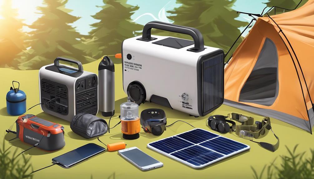
- Portable power stations: Convenient, UL/listed units with integrated BMS and inverter. Fast to deploy; limited expandability and DC integration.
- Dedicated systems: More flexible and expandable, can support hard-wired DC circuits and large inverters, but require design, wiring, mounting, and possibly a pro for safe installation.
Worked illustrative example
Illustrative only — do your own inventory.
- Daily loads: fridge 800 Wh + lights/phones 200 Wh + fan 200 Wh = 1,200 Wh/day.
- Autonomy: 2 cloudy days → energy reserve = 2,400 Wh.
- Battery usable fraction (manufacturer spec): 80% usable → required nominal ≈ 2,400 ÷ 0.8 = 3,000 Wh (3 kWh nameplate).
- Local PSH (winter conservative) = 3.0 hours. System derate estimate = 0.7 (accounting for losses and shading) → Required PV watts ≈ 1,200 ÷ (3.0 × 0.7) ≈ 571 W. Round up and consider tilt/moveable panels or adding capacity for winter.
- Controller: choose MPPT rated for the array voltage/current and the battery charging current (e.g., 30–60 A class depending on battery voltage).
- Inverter: size for continuous AC loads and check surge ratings for compressors; remember a 1,000 W AC draw at 12 V may require ~100 A DC plus losses.
Safe installation checklist
- Overcurrent protection sized for the source and conductor, with main battery protection near the battery.
- Proper cable sizing based on current, length (round-trip), temperature, and acceptable voltage drop; avoid universal wire-gauge recommendations without calculations (see Blue Sea guidance).
- Secure, insulated, strain‑relieved terminations; label disconnects and service points.
- Follow battery manufacturer rules for enclosure, ventilation, mounting, and temperature control—especially cold-temperature charging limits for LFP products.
- Any 120 V AC shore-power or transfer equipment work should be reviewed or performed by a qualified electrician; AHJ determines applicable code edition (NFPA 70 adoption varies by jurisdiction).
Troubleshooting highlights
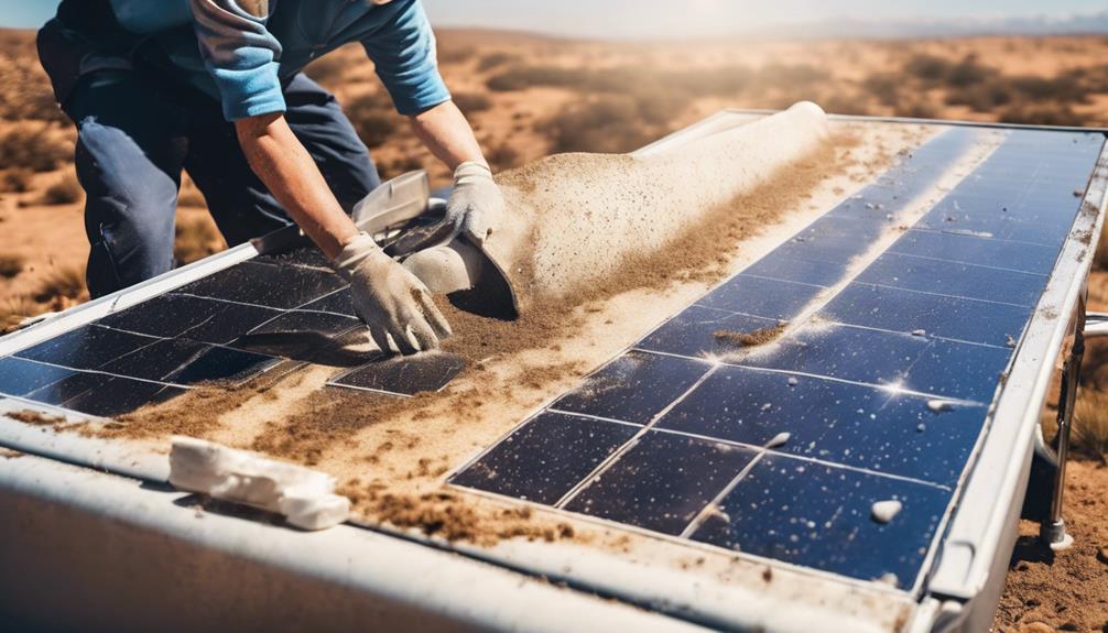
- Low yield: check tilt, shade, panel cleanliness, and PSH expectations for the season.
- Battery not charging: verify PV open-circuit voltage, controller settings, BMS cutouts (temperature or SOC), and cable/fuse integrity.
- Inverter won’t start motor loads: check surge capability, battery voltage under load, and inverter DC input current.
- Unexpected overnight drain: look for DC loads, parasitic draws, or incorrect switchgear.
When to hire a professional
Get a qualified electrician or RV tech for 120 V AC work, shore-power or transfer-switch changes, structural roof penetrations or complex roof mounts, high-current battery banks, code/permitting questions, or if you are unsure about grounding, bonding, or protection. The AHJ enforces the adopted code edition—confirm requirements locally (see NFPA/NFPA 70 adoption info).
Sources and tools to consult: NREL PVWatts for site PSH estimates, DOE guidance on solar-plus-storage, battery manuals for LFP temperature limits, and marine/RV wiring references (e.g., Blue Sea) for conductor and voltage-drop calculations.