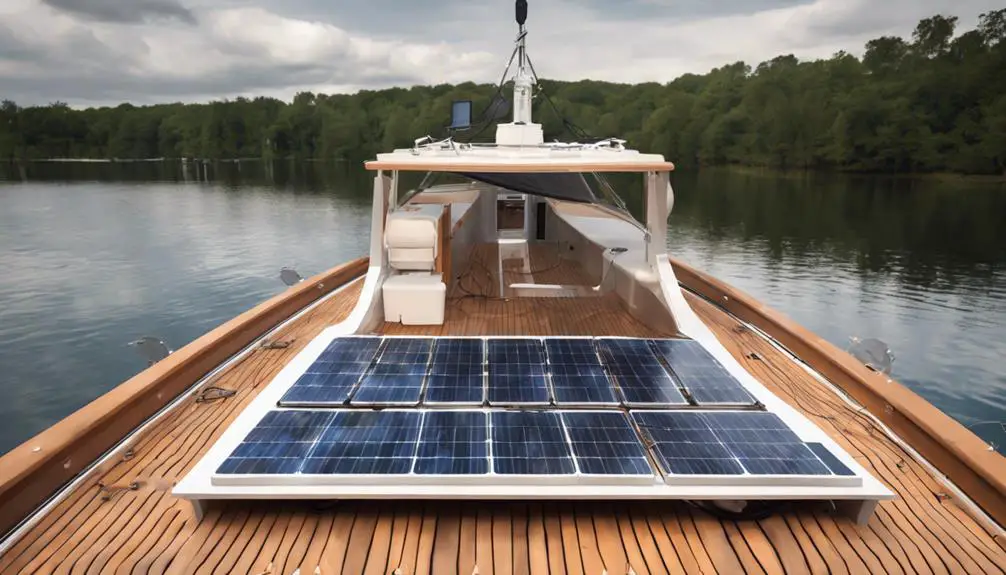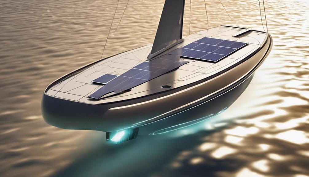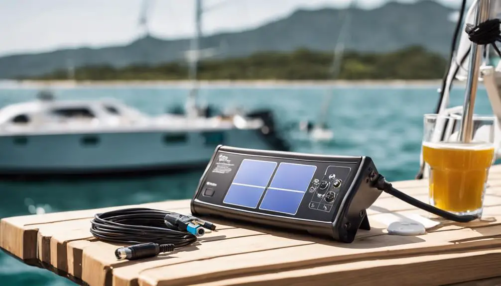
Introduction
Solar on a boat is more than panels and a few wires. A marine solar installation is a complete DC charging system: choose accessories to match the vessel’s battery bank, PV array, cable routing, charging sources, protection needs, and service environment. This guide helps cruising sailboat, trawler, and small powerboat owners decide what is essential, what depends on design, and what is optional.
Start with the boat’s electrical and physical plan
Before buying accessories, document:
- Battery-bank nominal voltage and chemistry (lead‑acid vs LFP/LiFePO4).
- PV module Voc and Isc, plus series/parallel layout of the PV array.
- Other charging sources: alternator, shore charger, inverter/charger, generator, DC‑to‑DC chargers.
- Cable routes, run lengths, chafe exposure, and service access.
- Shading, mounting locations, and ventilation for charge controllers.
Treat U.S. Coast Guard guidance, ABYC standards (E‑10, E‑11, E‑13, etc.), and manufacturer instructions as complementary inputs when planning installations.
The core accessory: the solar charge controller
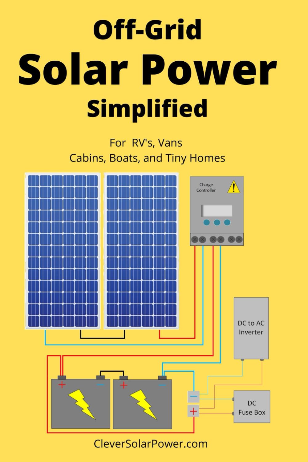
The controller is the system’s central device. Select one that is compatible with both sides of the system:
- Battery voltage and chemistry and the appropriate charge profiles.
- Maximum PV Voc (including cold‑temperature rise) and PV Isc.
- Maximum battery charge current, remote voltage/temperature sensing options, and any BMS or remote‑shutdown interface.
MPPT controllers accept higher PV voltages and often outperform PWM under many conditions, but PWM remains acceptable for small, voltage‑matched setups. Verify controller limits in the product manual rather than inferring capabilities from model names. Manufacturer procedures sometimes require a specific disconnect/connect sequence—Victron manuals are an example of product‑specific instructions.
Protection and service isolation
Separate PV‑side and battery‑side circuits when planning protection:
- PV‑side: protect array wiring and, where required by the design, individual parallel strings. A combiner box can centralize string fuses and make service easier but is not mandatory for every array.
- Battery‑side: protect controller output wiring to the battery or DC bus with OCPD (fuse or DC‑rated breaker) sized per the controller, conductor ampacity, and installation rules.
Install DC‑rated disconnects or isolators for service and emergency isolation. Do not substitute ordinary AC switches for DC PV circuits. A disconnect provides isolation; it does not replace overcurrent protection.
Marine wiring, connectors, and cable entry
- Use flexible, marine‑grade stranded copper conductors sized for ampacity, voltage drop, and routing conditions. Avoid generic wire size advice—choose based on your system data.
- Terminate with properly crimped lugs and adhesive‑lined heat shrink where appropriate. Provide strain relief and chafe protection along deck runs and at moving points.
- PV connectors are manufacturer‑specific. Do not cross‑mate different manufacturers’ connector families—the mating click is not proof of certification. Stäubli warns that mismatches raise contact resistance and failure risk.
- Use a watertight deck gland or cable gland for deck penetrations and back it with mechanical support; sealant alone is not sufficient.
Mounting and corrosion control
Choose panel brackets, rails, and fasteners to handle wind, vibration, walking loads, and impacts. Consider drainage, ventilation, and service access. Material compatibility and galvanic isolation matter in saltwater—”stainless” is not always the right answer unless you match metals and coatings correctly.
Monitoring and battery visibility
A shunt‑based battery monitor that measures current in and out of the battery gives a real state of charge (SoC) estimate and is especially useful on boats with multiple charging sources, lithium batteries, or heavy inverter use. If you install a shunt, route all relevant chargers and large loads through it; otherwise SoC will be incomplete. Controller displays and apps add PV voltage/current and charge‑stage info, but production readings do not equal energy stored—the whole system and measurement points matter.
Battery chemistry and coordination
Lead‑acid and LFP batteries need different controller settings and protections. LFP systems often require coordination with a BMS: the BMS can disable charging during faults or low temperatures, but it does not replace correct charger settings, proper fusing, or safe wiring. Some BMS implementations use a charge‑disconnect signal or networked control—confirm compatibility with the solar charger.
Accessory categories at a glance
Generally necessary
- Compatible solar charge controller
- Marine conductors and proper terminations
- Appropriate OCPD on battery‑side and PV‑side as required by design
- DC‑rated disconnects/isolators for service
- Mounting hardware and watertight cable entry (deck glands)
Design‑dependent
- PV string fuses and combiner box
- Remote voltage or temperature sensors
- BMS communication or charge‑disconnect interface
- Additional disconnects for separate battery banks or chargers
Often worthwhile but optional
- Shunt‑based battery monitor and remote displays
- Production logging and network monitoring
- Spare connectors and a small service kit
Maintenance and serviceability
Design accessory choices for inspection and service. Periodically check panel surfaces and junction boxes, mounts and fasteners, cable chafe, deck glands, connector locks, and OCPD condition. Accessible routing and labeled conductors reduce time and cost for future troubleshooting.
Safety note
For high‑voltage PV arrays, multi‑source charging systems, lithium battery installations, or work involving structural/deck modifications, engage a qualified marine electrician. Follow ABYC standards, U.S. Coast Guard guidance, and manufacturer instructions. Product manuals (for example, Victron MPPT and SmartShunt documentation) and connector manufacturers (for example, Stäubli) contain product‑specific procedures and limits—use them as authoritative inputs during installation.
Buy accessories to match the complete system—not simply the panel wattage—and prioritize serviceability, correct protection, and documented compatibility.