What boat solar can — and cannot — do
Solar can meaningfully reduce engine, generator, or shore-power charging and can maintain a house bank during storage, but it is not an automatic replacement for high-power inverter loads or an alternator-sized charging source. Whether a modest PV array keeps up with consumption depends on array size, shading, season, latitude, panel orientation, boat motion, battery condition, and your load profile. Treat large inverter loads (air conditioning, electric cooking, water heating, power tools) as a separate design problem.
System overview
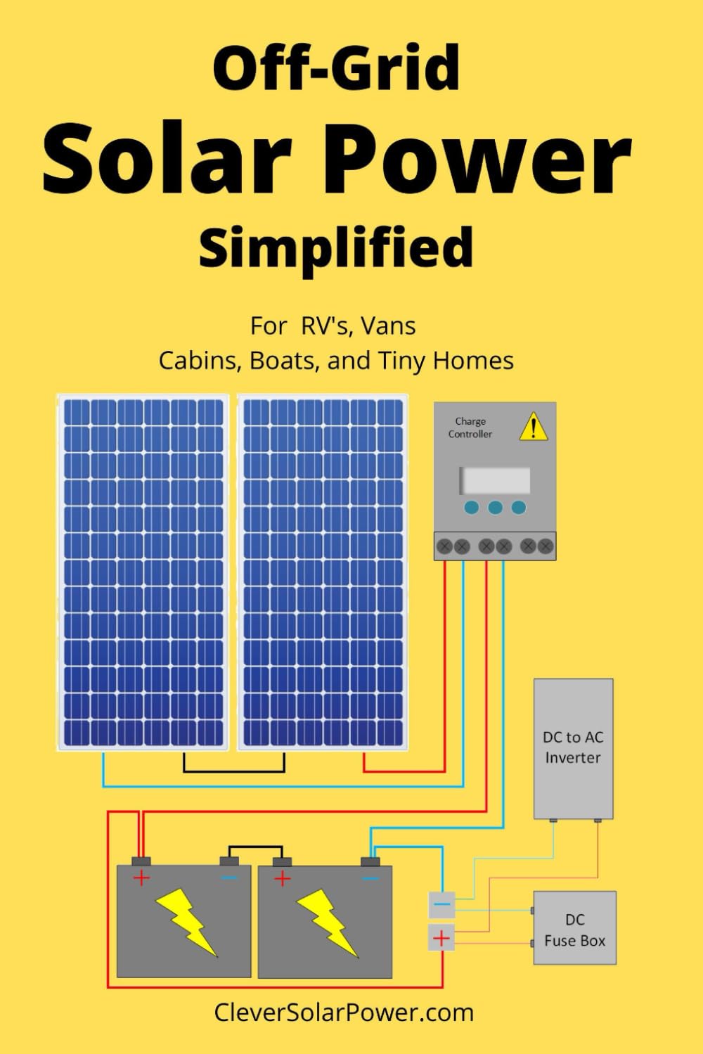
Typical flow: PV module(s) (the PV array) → solar charge controller → overcurrent protection / disconnects as required → house bank. Monitoring devices (solar controller logging and a battery monitor with a shunt) provide complementary views: the controller reports PV-side production; the shunt-based monitor shows net battery current.
Step 1: Start with a load audit
- List each DC load and AC-through-inverter load.
- Record operating watts or amps and typical runtime.
- Compute daily watt-hours for each item; sum to a daily total.
- Add margins for conversion losses (inverter inefficiency), charging inefficiency, and weather-related variability.
For planning, use actual equipment specifications and note that nominal voltage is not the same as operating voltage during charge/discharge cycles.
Step 2: Estimate seasonal PV production
Use a tool such as NREL’s PVWatts for a first-pass, modeling your cruising or storage location and reviewing monthly outputs. Adjust conservatively for shading, non-optimal tilt, soiling, heat, motion, and cloudy seasons. Validate the design with measured daily PV yield after installation.
Step 3: Survey mounting locations and shading
Map shade sources across times of day and seasons—mast, radar, antennas, boom, sails and rigging. Partial shading can disproportionately reduce output, especially with series-connected modules. Where shade patterns differ materially, consider separate arrays or multiple controller inputs rather than one string.
Step 4: Choose PV modules and mounting method
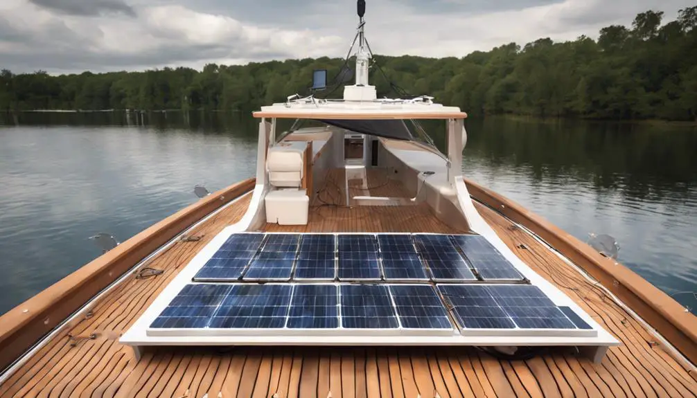
- Compare rigid, semi-flexible, and portable panels for usable wattage per available area, ventilation, weight, wind loading, and serviceability.
- Insist on documented environmental ratings, installation instructions, warranty conditions, and appropriate mounting hardware rather than marketing claims of being “marine.”
- Plan structural backing for fastener loads and protect cable penetrations against water ingress with proper glands and strain relief.
Step 5: Match the controller to the array and battery
Verify controller limits before finalizing the array: maximum PV operating voltage and Cold Voc, maximum PV input current (Isc considerations), maximum charging current, supported battery nominal voltage, and supported charging profiles. Determine whether an MPPT controller is justified by array voltage, shading, available cost, and controller limits; MPPT is often advantageous but not always the right choice. Follow the controller manual for connection and configuration sequence.
Step 6: Account for battery chemistry—especially LiFePO₄
- Flooded lead-acid, AGM, gel, and LiFePO₄ require different charging voltages, temperature limits, and maintenance approaches.
- For LiFePO₄, follow the battery manufacturer’s exact charging voltage, current, temperature limits, and storage instructions. Confirm whether charging is restricted at low temperatures.
- Do not treat the BMS as a substitute for properly configured chargers, fuses, disconnects, and system-level protection.
Step 7: Wiring, protection, and marine installation details
Design protection around the conductors and equipment: fuses and breakers protect conductors and equipment from fault current and must be sized per conductor ampacity, equipment instructions, and applicable standards. The battery-side connection is a high-consequence point and requires carefully located protection. PV-side disconnects and overcurrent protection depend on array configuration and manufacturer instructions—there is no universal rule.
Use marine-grade, stranded, tinned copper conductor, corrosion-resistant terminals, proper crimping tools, sealed cable entries, drip loops, strain relief, and chafe protection. Respect the boat’s existing bonding, grounding, and DC negative return architecture; do not create ad hoc arrangements.
Step 8: Commissioning
- Complete and label a one-line diagram.
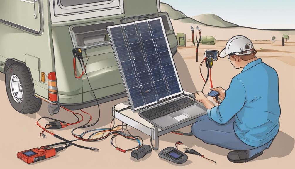
- Check polarity and continuity with test equipment.
- Verify conductor sizes, terminations, strain relief, and protection placement.
- Confirm battery chemistry and controller settings per manuals.
- Energize following the controller manual and record baseline PV yield and battery-monitor readings.
- Inspect for heating, loose connections, or water-entry paths.
Monitoring, maintenance, and troubleshooting
- Monitor battery voltage, charge/discharge current (shunt), configured state of charge, daily PV yield, controller status, and battery/BMS alarms.
- Maintenance: clean modules per manufacturer, inspect mounts, glands, connectors, and look for corrosion, chafe, or heat discoloration.
- Troubleshooting order (illustrative): check battery state and protection → controller status → PV voltage at controller in daylight → polarity/connectors → shading/soiling/damage → BMS interventions.
When to obtain professional review
Obtain an ABYC-trained or otherwise qualified marine electrical professional for high-voltage arrays, lithium conversions, inverter/charger integration, alternator integration, complex bonding/grounding, substantial structural changes, or when insurance/survey requirements apply. ABYC standards E-10, E-11, and E-13 are relevant—consult the current ABYC Standards Library and equipment manuals for final decisions.
Compact pre-installation checklist (MERGE)
- Completed load audit and conservative PV production estimate by month.
- Shade map and chosen mounting strategy with structural backing plan.
- Controller selected with verified Voc/Cold Voc, Isc, and charge-current ratings.
- Battery chemistry and charging profile confirmed; BMS interactions considered.
- Wiring plan using marine-grade, stranded, tinned copper conductor with protection and labeled one-line diagram.
- Plan for commissioning tests, baseline yield logging, and maintenance schedule.
Illustrative worked example (non-prescriptive)
As an example only: a liveaboard owner performs a load audit showing modest daily DC usage (navigation lights, instruments, LED cabin lights, a small refrigerator cycling). They map shading, choose roof-mounted rigid panels where ventilation is possible, select a controller after verifying Cold Voc and input-current limits, and add a battery monitor with shunt. After commissioning they log daily PV yield for a month and compare to their estimate, then adjust habits and shading mitigation to improve net charging. Any step involving LiFePO₄ conversion or alternator integration is reviewed by a qualified marine electrician.
Warning: High-voltage PV arrays, lithium conversions, inverter/charger integration, alternator integration, complex bonding/grounding, and structural modifications create risk and should receive qualified professional review. Manuals, battery datasheets, insurance requirements, and ABYC standards must control the final installation.