Introduction
An off‑grid solar-electric system stores daylight as usable electricity so you can run lights, pumps, refrigeration, electronics and small appliances without a utility connection. This guide focuses on practical planning and safety for small standalone systems used in RVs and travel trailers, camper vans, cabins, boats and tiny homes. It explains how to estimate loads, pick voltages and components, size panels and batteries, and integrate shore power, a generator or alternator charging.
How an off‑grid solar system works
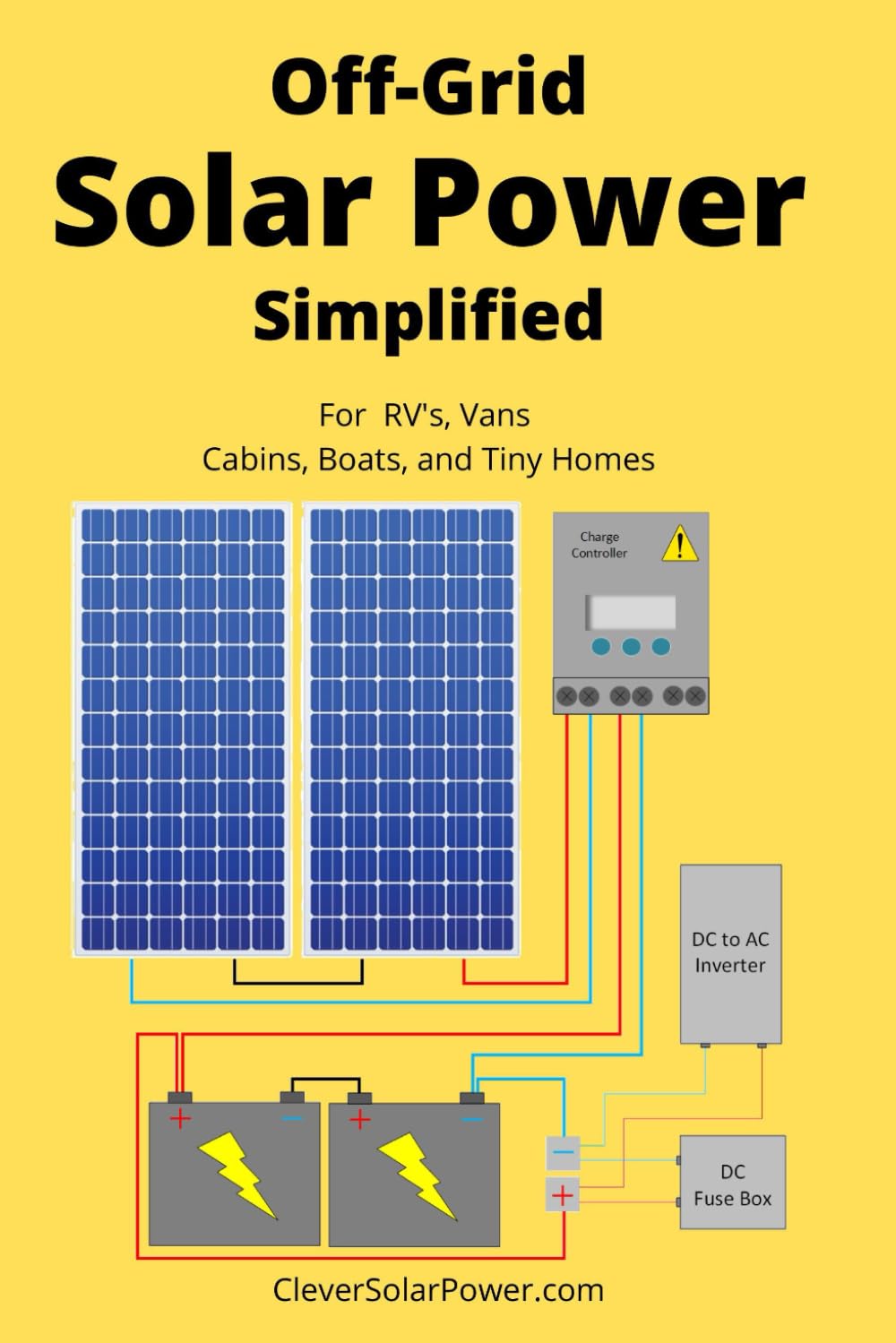
Key components and flow of energy:
- PV module (solar panel) → PV disconnect/overcurrent protection → charge controller → battery bank
- Battery bank → DC loads and/or inverter → AC loads
- Optional inputs: shore power or generator via an inverter‑charger, and vehicle alternator via a DC‑to‑DC charger
Definitions on first use: a PV module (also called a solar panel) converts sunlight into direct current (DC); an inverter converts DC into alternating current (AC). A battery management system (BMS) protects many lithium packs; a grid‑forming inverter can create an independent AC waveform for standalone operation.
The four questions that determine system size
- What loads must be powered? (what and how long)
- How many watt‑hours (Wh) do those loads use per day?
- What instantaneous power (watts) and surge (starting) power will be needed?
- How much autonomy—how many cloudy days—should the battery bank cover?
Calculate daily energy use (start with loads)
List each appliance, its running watts, hours per day and compute watt‑hours: Watts × Hours = Watt‑hours.
| Appliance | Watts | Hours/day | Wh/day |
|---|---|---|---|
| LED lights | 30 | 4 | 120 |
| 12V fridge (average) | 60 | 8 | 480 |
| Laptop (AC) | 60 | 3 | 180 |
Example (illustrative): total daily load = 2,000 Wh. Decide desired autonomy = 2 days. Assume system losses and reserve (inverter losses, charge losses, DoD reserve) of ~30% as a planning margin. Battery energy required = 2,000 Wh/day × 2 days ÷ (1 − 0.30) ≈ 5,714 Wh (5.7 kWh usable target).
Choose the battery bank
Convert Wh to amp‑hours (Ah) using the selected system voltage: Wh = volts × Ah. Example: at 12 V, 5,714 Wh ≈ 476 Ah (12 V × 476 Ah ≈ 5,712 Wh). At 24 V, Ah requirement halves (~238 Ah). Usable capacity depends on chemistry and allowable depth of discharge (DoD). Lead‑acid types (flooded, AGM, gel) typically recommend shallower DoD (e.g., 50%) than LiFePO4 (LFP) which often allows 80–90% usable, but LFP has low‑temperature charging limits and requires a BMS. Real usable energy will be lower after conversion losses, temperature effects and aging—plan a margin and follow manufacturer specs.
Voltage tradeoffs: 12 V keeps compatibility with many RV and marine systems but increases current and conductor size. 24 V or 48 V reduces current and voltage drop for the same power but may require different chargers, inverters and equipment.
Size the solar array
Begin with the daily energy target and use a location‑specific solar resource (peak sun hours for the worst operating month, not only the annual average). Account for system losses (panel soiling, wiring, controller and temperature) and tilt, shade and roof area limits. Illustrative calculation: to replace 2,000 Wh/day, if you expect 4 peak sun hours and assume 70% system efficiency (30% losses), required PV ≈ 2,000 ÷ (4 × 0.70) ≈ 714 W of panels. Use tools such as NREL PVWatts or local insolation data for a refined estimate.
Select the charge controller
PWM (pulse‑width modulation) controllers are simple and can work where panel voltage closely matches battery voltage. MPPT (maximum power point tracking) controllers are more flexible and can extract more energy from higher‑voltage arrays, long cable runs or cold conditions. Choose a controller rated for your array’s open‑circuit voltage (VOC) and short‑circuit current (ISC) with headroom for temperature effects and future expansion.
Choose the inverter
For mixed loads, prefer a pure‑sine‑wave inverter. Specify both continuous and surge ratings to handle starting motors or compressors. For standalone AC, use a grid‑forming inverter or an inverter‑charger designed for off‑grid use. Consider idle consumption, efficiency, AC transfer behavior and neutral‑ground bonding requirements for your application. Sensitive electronics and medical devices may require a stable waveform and low distortion.
Wire, fuse and disconnect the system safely
Voltage drop matters—long runs and undersized conductors reduce charging voltage, increase heat and waste energy. Conductor selection depends on maximum continuous current, circuit length (round trip), allowable voltage drop, ambient temperature and installation method. Every battery circuit needs appropriate overcurrent protection: a main battery fuse or breaker close to the positive terminal, branch protection, PV overcurrent protection and service disconnects. Panels must never be connected directly to batteries—a charge controller is required.
Add shore power, generator or alternator charging
Shore power and generators typically use an inverter‑charger to charge batteries and supply AC loads. Vehicle alternator charging should be controlled—use a DC‑to‑DC charger or an approved isolator designed to work with smart alternators and the battery chemistry. Direct, unmanaged alternator connections can overheat the alternator or damage batteries and are not a universal solution.
Monitoring, maintenance and common mistakes
Use a proper battery monitor with a shunt for reliable coulomb‑counting SOC estimates; battery voltage alone is an unreliable SOC indicator while charging or under load. Inspect terminals, fuses and cable terminations regularly; protect wiring from chafe, vibration and moisture. Common mistakes include sizing from panel watts alone, omitting a main battery fuse, undersizing conductors, and ignoring winter or regional worst‑case solar output.
When to hire a professional
Get a licensed electrician, RV technician or marine electrician for permanent AC wiring, service‑panel integration, high‑current systems, marine installations, structural roof work or any installation requiring permits, inspections or insurance approvals. Follow local electrical code, manufacturer instructions and safety standards.
Conclusion
Design sequence: measure loads → choose autonomy and voltage → size the battery (Wh and Ah) → model solar production for your worst month → select charge controller and inverter → protect and wire with correct fusing and conductors → add controlled alternator/shore/generator charging → monitor and test. Safety, realistic energy accounting and adherence to manufacturer and code requirements are as important as the hardware itself.
Safety note: Batteries and high‑current DC circuits present fire and shock hazards; lithium batteries can experience thermal runaway if misused. Always follow manufacturer instructions, use proper protection devices, and consult qualified professionals when in doubt.